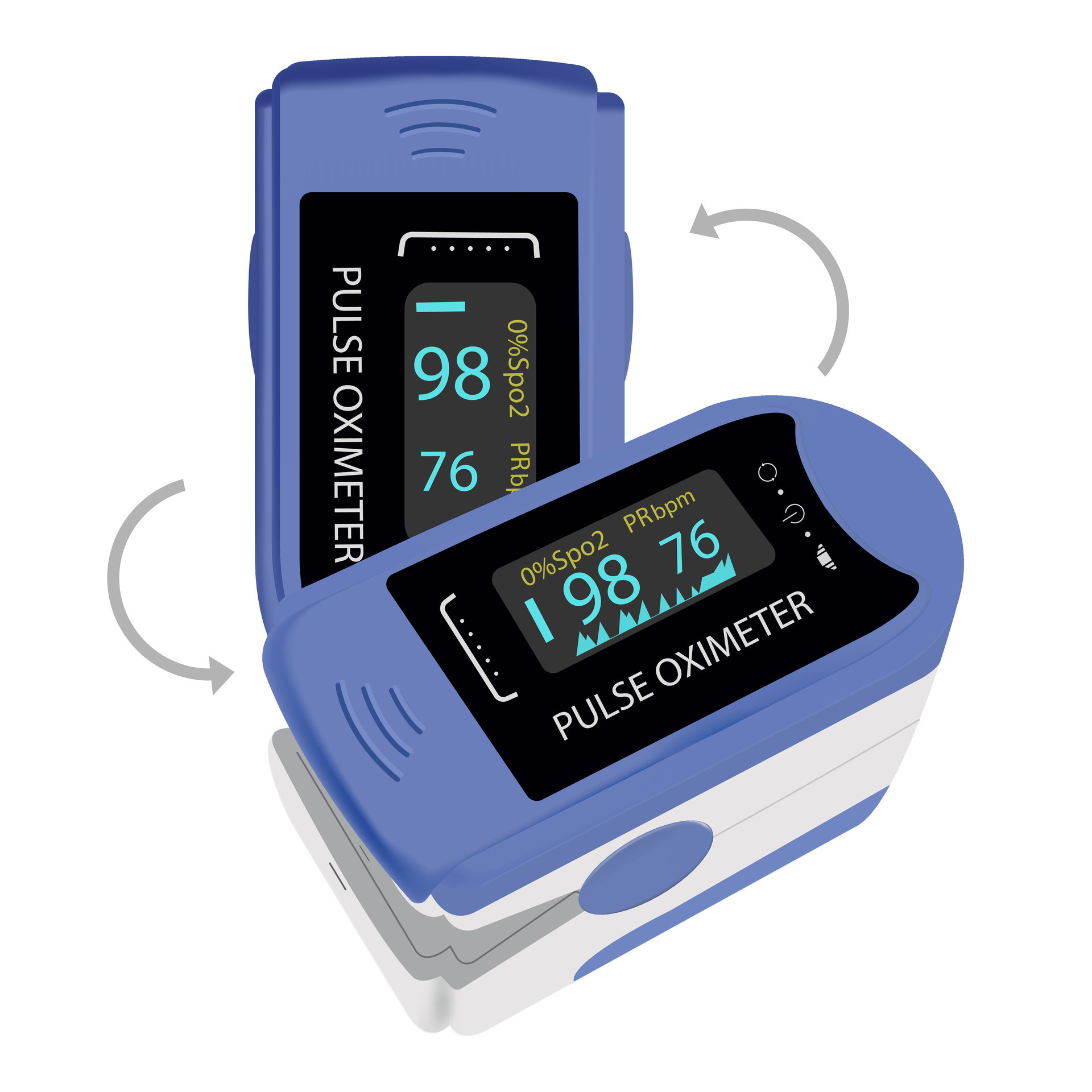
How To Make DIY Heart Rate Monitor Circuit Diagram The MAX30102 heart rate and oxygen sensor operates based on the principle of light absorption by blood in tissues and blood vessels. MAX30102 utilizes infrared (IR) and red light reflection technology to measure the oxygen saturation (SpO2) and heart rate (HR) of the user.

This project aims to build a compact, DIY heart rate and oxygen saturation monitor using the MAX30100 sensor, an Arduino, and a 16x2 LCD. The MAX30100 is a pulse oximeter and heart-rate sensor, which works by shining infrared and red light through the skin to detect changes in blood oxygen levels and heartbeats. How It Works
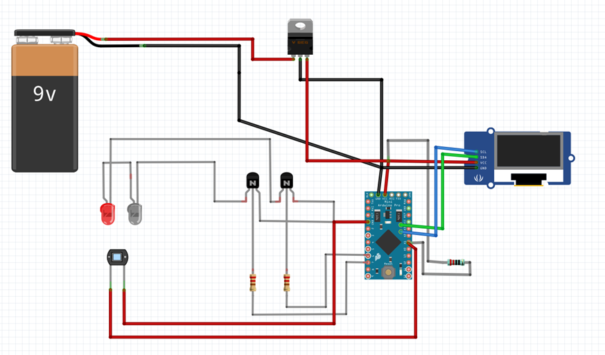
Smart Blood Oxygen And Heart Rate Monitor With Automatic Data Saving System Circuit Diagram
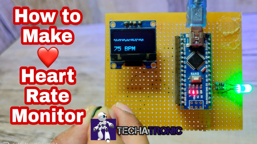
DIY heart rate monitor and pulse oximeter using MAX30100 Pulse Oximeter Heart Rate Sensor Module. May 2, 2021
The portable health monitor tracks a user's pulse rate, oxygen level, body temperature, and heart rate. ESP32 receives the raw ECG value from the output terminal of the AD8232 ECG sensor. This value is obtained at the analog input pin of ESP32. The MLX90614 and MAX30100 sensors communicate their values through the I2C interface. The heart of this DIY heart health monitor is the MAX30105 sensor, which is specially designed to measure heart rate and SpO2 (blood oxygen saturation). This sensor uses photo plethysmography (PPG) to detect changes in blood volume by shining LED light (red, infrared, and green) through your skin and measuring how much light is absorbed.

Guide to Using MAX30102 Heart Rate and Oxygen Sensor With Arduino Circuit Diagram
In this project, I will guide you in creating a simple health-monitoring device. That measures heart rate and oxygen saturation (SpO2) and displays the data on an I2C LCD screen. By simply placing your finger on the sensor, the device will show your heart rate and SpO2.